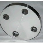
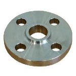
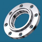
Weld Neck Raised Face (WNRF) Flange.
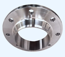
The weld neck flange derives its name from the neck portion of the flange that is welded to the end of a piping system. Weld Neck Flanges have a long tapered hub and are often used for high pressure applications. It is designed to transfer stress to the pipe, thereby reducing high stress concentrations at the base of the flange. Weld Neck flanges are costlier due to their design and engineering, and increased material
The three most common types of facings for weld neck flanges are raised face (most common), flat face, and ring type joint (RTJ). When ordering a weld neck flange, it is important to specify the schedule pipe is being used for. This is because the inside diameter of the flange will match the inside diameter of your pipe. The butt-weld joint this flange has with the pipe along with the tapered hub, makes this flange very resistant to dishing and a very sturdy connection. These flanges are ideal for extreme fluctuations of temperature and in environments where there may be a lot of bending and handling of the flanges.
These Flanges are available in the following range.
Stainless Steel: ASTM A182 F304, F304L, F304H, F316, F316L, F316Ti, F310, F310S, F321, F321H, F317, F347, F347H, F904L.
Duplex Stainless Steel: UNS S31803, UNS S32750
Carbon Steel: ASTM A105,
Alloy Steel: ASTM A182 F1, F11, F22, F5, F9, F91
Nickel Alloys: Monel 400 & 500, Inconel 600 & 625, Incoloy 800, 825, Hastelloy C22, C276
Copper Alloys: Copper, Brass & Gunmetal
Size: 1/8″ NB TO 48″NB.
Class: 150#, 300#, 400#, 600#, 900#, 1500#, 2500#
Sch: 5s, 10s, 10, 20, 40s, 40, STD, 60, 80s, 80, XS, 100, 120, 140, 160, XXS
Dimensional Standard
ANSI: ANSI B16.5, ANSI B16.47, MSS SP44, ANSI B16.36, ANSI B16.48
DIN: DIN 2527, DIN 2566, DIN 2573, DIN 2576, DIN 2641, DIN 2642, DIN 2655, DIN 2656, DIN 2627, DIN 2628, DIN 2629, DIN 2631, DIN 2632, DIN 2633, DIN 2634, DIN 2635, DIN 2636, DIN 2637, DIN 2638, DIN 2673
B.S: BS 4504, BS4504, BS1560, BS10
| DIMENSIONS OF CLASS 150 FLANGES AS PER ANSI B 16.5 | ||||||||||
| NB | A | D | B | G | K | O | H | L | No. of Holes | |
| 1/2 ” | 15 | 30.2 | 88.9 | 11.1 | 34.9 | 60.3 | 21.3 | 47.6 | 15.9 | 4 |
| 3/4 ” | 20 | 38.1 | 98.4 | 12.7 | 42.9 | 69.8 | 26.7 | 52.4 | 15.9 | 4 |
| 1” | 25 | 49.2 | 107.9 | 14.3 | 50.8 | 79.4 | 33.4 | 55.6 | 15.9 | 4 |
| 1 1/4 ” | 32 | 58.7 | 117.5 | 15.9 | 63.5 | 88.9 | 42.2 | 57.1 | 15.9 | 4 |
| 1 1/2 ” | 40 | 65.1 | 127.0 | 17.5 | 73.0 | 98.4 | 48.3 | 61.9 | 15.9 | 4 |
| 2” | 50 | 77.8 | 152.4 | 19.0 | 92.1 | 120.6 | 60.3 | 63.5 | 19.0 | 4 |
| 2 1/2 ” | 65 | 90.5 | 177.8 | 22.2 | 104.8 | 139.7 | 73.0 | 69.8 | 19.0 | 4 |
| 3” | 80 | 107.9 | 190.5 | 23.8 | 127.0 | 152.4 | 88.9 | 69.8 | 19.0 | 4 |
| 4” | 100 | 134.9 | 230.0 | 23.8 | 157.2 | 190.5 | 114.3 | 76.2 | 19.0 | 8 |
| 5” | 125 | 163.5 | 254.0 | 23.8 | 185.7 | 215.9 | 141.3 | 88.9 | 22.2 | 8 |
| 6” | 150 | 192.1 | 279.4 | 25.4 | 215.9 | 241.3 | 168.3 | 88.9 | 22.2 | 8 |
| 8” | 200 | 246.1 | 342.9 | 28.6 | 269.9 | 298.4 | 219.1 | 101.6 | 22.2 | 8 |
| 10” | 250 | 304.8 | 406.4 | 30.2 | 323.8 | 361.9 | 273.0 | 101.6 | 25.4 | 12 |
| 12” | 300 | 365.1 | 482.6 | 31.8 | 381.0 | 431.8 | 323.9 | 114.3 | 25.4 | 12 |
| 14” | 350 | 400.0 | 533.4 | 34.9 | 412.7 | 476.2 | 355.6 | 127.0 | 28.6 | 12 |
| 16” | 400 | 457.2 | 596.9 | 36.5 | 469.9 | 539.7 | 406.4 | 127.0 | 28.6 | 16 |
| 18” | 450 | 504.8 | 635.0 | 39.7 | 533.4 | 577.8 | 457.2 | 139.7 | 31.7 | 16 |
| 20” | 500 | 558.8 | 698.5 | 42.9 | 584.2 | 635.0 | 508.0 | 144.5 | 31.7 | 20 |
| 24” | 600 | 663.6 | 812.8 | 47.6 | 692.1 | 749.3 | 609.6 | 152.4 | 34.9 | 20 |
| DIMENSIONS OF CLASS 300 FLANGES AS PER ANSI B 16.5 | ||||||||||
| NB | A | D | B | G | K | O | H | L | No. of Holes | |
| 1/2 ” | 15 | 38.1 | 95.2 | 14.3 | 34.9 | 66.7 | 21.3 | 52.4 | 15.9 | 4 |
| 3/4 ” | 20 | 47.6 | 117.5 | 15.9 | 42.9 | 82.5 | 26.7 | 57.1 | 19.0 | 4 |
| 1” | 25 | 54.0 | 123.8 | 17.5 | 50.8 | 88.9 | 33.4 | 61.9 | 19.0 | 4 |
| 1 1/4 ” | 32 | 63.5 | 133.3 | 19.0 | 63.5 | 98.4 | 42.2 | 65.1 | 19.0 | 4 |
| 1 1/2 ” | 40 | 69.8 | 155.6 | 20.6 | 73.0 | 114.3 | 48.3 | 68.3 | 22.2 | 4 |
| 2” | 50 | 84.1 | 165.1 | 22.2 | 92.1 | 127.0 | 60.3 | 69.8 | 19.0 | 8 |
| 2 1/2 ” | 65 | 100.0 | 190.5 | 25.4 | 104.8 | 149.2 | 73.0 | 76.2 | 22.2 | 8 |
| 3” | 80 | 117.5 | 209.5 | 28.6 | 127.0 | 168.3 | 88.9 | 79.4 | 22.2 | 8 |
| 4” | 100 | 146.0 | 254.0 | 31.8 | 157.2 | 200.0 | 114.3 | 85.7 | 22.2 | 8 |
| 5” | 125 | 177.8 | 279.4 | 34.9 | 185.7 | 234.9 | 141.3 | 98.4 | 22.2 | 8 |
| 6” | 150 | 206.4 | 317.5 | 36.5 | 215.9 | 269.9 | 168.3 | 98.4 | 22.2 | 12 |
| 8” | 200 | 260.3 | 381.0 | 41.3 | 269.9 | 330.2 | 219.1 | 111.1 | 25.4 | 12 |
| 10” | 250 | 320.7 | 444.5 | 47.6 | 323.8 | 387.3 | 273.0 | 117.5 | 28.6 | 16 |
| 12” | 300 | 374.6 | 520.7 | 50.8 | 381.0 | 450.8 | 323.9 | 130.2 | 31.7 | 16 |
| 14” | 350 | 425.4 | 584.2 | 54.0 | 412.7 | 514.3 | 355.6 | 142.9 | 31.7 | 20 |
| 16” | 400 | 482.6 | 647.7 | 57.2 | 469.9 | 571.5 | 406.4 | 146.0 | 34.9 | 20 |
| 18” | 450 | 533.4 | 711.2 | 60.3 | 533.4 | 628.5 | 457.2 | 158.7 | 34.9 | 24 |
| 20” | 500 | 587.4 | 774.7 | 63.5 | 584.2 | 685.8 | 508.0 | 161.9 | 34.9 | 24 |
| 24” | 600 | 701.7 | 914.4 | 69.8 | 692.1 | 812.8 | 609.6 | 168.3 | 41.3 | 24 |
| DIMENSIONS OF CLASS 600 FLANGES AS PER ANSI B 16.5 | ||||||||||
| NB | A | D | B | G | K | O | H | L | No. of Holes | |
| 1/2 ” | 15 | 38.1 | 95.2 | 14.3 | 34.9 | 66.7 | 21.3 | 52.4 | 15.9 | 4 |
| 3/4 ” | 20 | 47.6 | 117.5 | 15.9 | 42.9 | 82.5 | 26.7 | 57.1 | 19.0 | 4 |
| 1” | 25 | 54.0 | 123.8 | 17.5 | 50.8 | 88.9 | 33.4 | 61.9 | 19.0 | 4 |
| 1 1/4 ” | 32 | 63.5 | 133.3 | 20.6 | 63.5 | 98.4 | 42.2 | 66.7 | 19.0 | 4 |
| 1 1/2 ” | 40 | 69.8 | 155.6 | 22.2 | 73.0 | 114.3 | 48.3 | 69.8 | 22.2 | 4 |
| 2” | 50 | 84.1 | 165.1 | 25.4 | 92.1 | 127.0 | 60.3 | 73.0 | 19.0 | 8 |
| 2 1/2 ” | 65 | 100.0 | 190.5 | 28.6 | 104.8 | 149.2 | 73.0 | 79.4 | 22.2 | 8 |
| 3” | 80 | 117.5 | 209.5 | 31.8 | 127.0 | 168.3 | 88.9 | 82.5 | 22.2 | 8 |
| 4” | 100 | 152.4 | 273.0 | 38.1 | 157.2 | 215.9 | 114.3 | 101.6 | 25.4 | 8 |
| 5” | 125 | 188.9 | 330.2 | 44.4 | 185.7 | 266.7 | 141.3 | 114.3 | 28.6 | 8 |
| 6” | 150 | 222.2 | 355.6 | 47.6 | 215.9 | 292.1 | 168.3 | 117.6 | 28.6 | 12 |
| 8” | 200 | 273.0 | 419.1 | 55.6 | 269.9 | 349.2 | 219.1 | 133.3 | 31.7 | 12 |
| 10” | 250 | 342.9 | 508.0 | 63.5 | 323.8 | 431.8 | 273.0 | 152.4 | 34.9 | 16 |
| 12” | 300 | 400.0 | 558.8 | 66.7 | 381.0 | 488.9 | 323.9 | 155.6 | 34.9 | 20 |
| 14” | 350 | 431.8 | 603.2 | 69.9 | 412.7 | 527.0 | 355.6 | 165.1 | 38.1 | 20 |
| 16” | 400 | 495.3 | 685.8 | 75.2 | 469.9 | 603.2 | 406.4 | 177.8 | 41.3 | 20 |
| 18” | 450 | 546.0 | 742.9 | 82.6 | 533.4 | 654.0 | 457.2 | 184.1 | 44.4 | 20 |
| 20” | 500 | 609.6 | 812.8 | 88.9 | 584.2 | 723.9 | 508.0 | 190.5 | 44.4 | 24 |
| 24” | 600 | 717.6 | 939.8 | 101.6 | 692.1 | 838.2 | 609.6 | 203.2 | 50.8 | 24 |