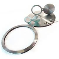
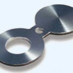
Spectacle Blind Flange

It is generally a piece of metal that is cut to fit between two pipe flanges and usually sandwiched between two gaskets. a spectacle blind is often made from two metal discs that are attached to each other by a small section of steel. The shape is similar to a pair of glasses or “spectacles” – hence the name spectacle blind. One end of the blind will have an opening to allow flow through the pipe during operation and the other end is solid to block flow during maintenance. They are generally installed as a permanent device to separate process piping systems.
The whole idea of a spectacle blind is so that one can be absolutely sure that an item of equipment is properly and securely blanked off with no possibility of any flow or leakage through a valve during maintenance. The flow can be diverted to other items of equipment but not just bypassed around the blank as this would compromise the safety function of the spectacle blind. The flow has to valved off and pressure relieved prior to loosening flange bolts and swinging the blind.
These Flanges are available in the following range.
Stainless Steel: ASTM a182 F304, F304L, F304H, F316, F316L, F316Ti, F310, F310S, F321, F321H, F317, F347, F347H, F904L.
Duplex Stainless Steel: UNS S31803, UNS S32750
Carbon Steel: ASTM a105,
Alloy Steel: ASTM a182 F1, F11, F22, F5, F9, F91
Nickel Alloys: Monel 400 & 500, Inconel 600 & 625, Incoloy 800, 825, Hastelloy C22, C276
Copper Alloys: Copper, Brass & Gunmetal
Size: 1/8″ NB TO 48″NB.
Class: 150#, 300#, 400#, 600#, 900#, 1500#, 2500#
Dimensional Standard
ANSI: ANSI B16.5, ANSI B16.47, MSS SP44, ANSI B16.36, ANSI B16.48
DIN: DIN 2527, DIN 2566, DIN 2573, DIN 2576, DIN 2641, DIN 2642, DIN 2655, DIN 2656, DIN 2627, DIN 2628, DIN 2629, DIN 2631, DIN 2632, DIN 2633, DIN 2634, DIN 2635, DIN 2636, DIN 2637, DIN 2638, DIN 2673
B.S: BS 4504, BS4504, BS1560, BS10
| DIMENSIONS OF CLASS 150 FLANGES AS PER ANSI B 16.48 | ||||||||
| NB | a | B | C | D | E | T1 | T2 | |
| 1/2 ” | 15 | 48 | 14 | 60 | 26 | 5 | 4 | |
| 3/4 ” | 20 | 57 | 21 | 70 | 32 | 5 | 4 | |
| 1” | 25 | 67 | 27 | 79 | 38 | 5 | 4 | |
| 1 1/2 ” | 40 | 86 | 41 | 98 | 52 | 5 | 4 | |
| 2” | 50 | 105 | 52 | 120 | 20 | 64 | 6 | 4 |
| 3” | 80 | 137 | 78 | 152 | 20 | 86 | 8 | 6 |
| 4” | 100 | 175 | 103 | 190 | 20 | 114 | 9 | 7 |
| 6” | 150 | 222 | 154 | 241 | 22 | 148 | 12 | 10 |
| 8” | 200 | 279 | 203 | 298 | 22 | 188 | 15 | 12 |
| 10” | 250 | 340 | 254 | 362 | 26 | 154 | 18 | 15 |
| 12” | 300 | 410 | 303 | 432 | 26 | 190 | 21 | 18 |
| 14” | 350 | 451 | 343 | 476 | 30 | 208 | 23 | 20 |
| 16” | 400 | 515 | 394 | 540 | 30 | 176 | 25 | 23 |
| 18” | 450 | 550 | 445 | 578 | 33 | 188 | 28 | 26 |
| 20” | 500 | 605 | 495 | 635 | 33 | 162 | 31 | 29 |
| 24” | 600 | 720 | 597 | 749 | 36 | 194 | 37 | 34 |
| DIMENSIONS OF CLASS 300 FLANGES AS PER ANSI B 16.48 | ||||||||
| NB | a | B | C | D | E | T1 | T2 | |
| 1/2 ” | 15 | 54 | 14 | 66 | 30 | 5 | 4 | |
| 3/4 ” | 20 | 67 | 21 | 83 | 36 | 5 | 4 | |
| 1” | 25 | 73 | 27 | 89 | 42 | 5 | 4 | |
| 1 1/2 ” | 40 | 95 | 41 | 114 | 58 | 7 | 5 | |
| 2” | 50 | 111 | 52 | 127 | 20 | 68 | 8 | 6 |
| 3” | 80 | 149 | 78 | 168 | 22 | 96 | 11 | 8 |
| 4” | 100 | 181 | 103 | 200 | 22 | 118 | 13 | 10 |
| 6” | 150 | 251 | 154 | 270 | 22 | 112 | 18 | 15 |
| 8” | 200 | 308 | 203 | 330 | 26 | 138 | 23 | 19 |
| 10” | 250 | 362 | 254 | 387 | 30 | 118 | 27 | 24 |
| 12” | 300 | 422 | 303 | 451 | 33 | 138 | 32 | 28 |
| 14” | 350 | 486 | 343 | 514 | 33 | 124 | 35 | 33 |
| 16” | 400 | 540 | 394 | 571 | 36 | 140 | 39 | 37 |
| 18” | 450 | 595 | 445 | 628 | 36 | 126 | 44 | 42 |
| 20” | 500 | 655 | 495 | 686 | 36 | 140 | 49 | 47 |
| 24” | 600 | 775 | 597 | 813 | 42 | 168 | 58 | 56 |
| DIMENSIONS OF CLASS 600 FLANGES AS PER ANSI B 16.48 | ||||||||
| NB | a | B | C | D | E | T1 | T2 | |
| 1/2 ” | 15 | 54 | 14 | 66 | 30 | 5 | 4 | |
| 3/4 ” | 20 | 67 | 21 | 82 | 36 | 6 | 4 | |
| 1” | 25 | 73 | 27 | 89 | 42 | 7 | 4 | |
| 1 1/2 ” | 40 | 95 | 41 | 114 | 58 | 9 | 6 | |
| 2” | 50 | 111 | 52 | 127 | 20 | 68 | 11 | 8 |
| 3” | 80 | 149 | 78 | 168 | 22 | 96 | 15 | 12 |
| 4” | 100 | 194 | 103 | 216 | 26 | 126 | 18 | 15 |
| 6” | 150 | 267 | 154 | 292 | 30 | 116 | 24 | 21 |
| 8” | 200 | 321 | 203 | 349 | 33 | 140 | 31 | 27 |
| 10” | 250 | 400 | 254 | 432 | 36 | 128 | 38 | 33 |
| 12” | 300 | 457 | 303 | 489 | 36 | 114 | 44 | 39 |
| 14” | 350 | 492 | 343 | 527 | 39 | 122 | 48 | 44 |
| 16” | 400 | 565 | 394 | 603 | 42 | 144 | 55 | 53 |
| 18” | 450 | 613 | 445 | 654 | 45 | 155 | 62 | 60 |
| 20” | 500 | 682 | 495 | 724 | 45 | 140 | 68 | 67 |
| 24” | 600 | 790 | 597 | 838 | 52 | 164 | 81 | 80 |
All dimensions are in millimeters unless otherwise indicated.
General notes:
o D = Hole size (where required) should be the same as the flange bolt hole. In practice, these dimensions have been rounded round off upwards.
o T1 = Thickness Carbon Steel.
o T2 = Thickness Stainless Steel.
o W = Thickness of the web (or tie bar) should be 0.25 inch (6 mm) minimum, or equal to T1 and T2 if less than 0.25 inch (6 mm).
o Spectacle Blinds should be made from a plate or forging specification, approved for use by ASME B31.3, of essentially the same chemical composition as the mating flanges
and piping involved.
o Depending on a customer specification, the dimensions can be different from what on this page is defined.


